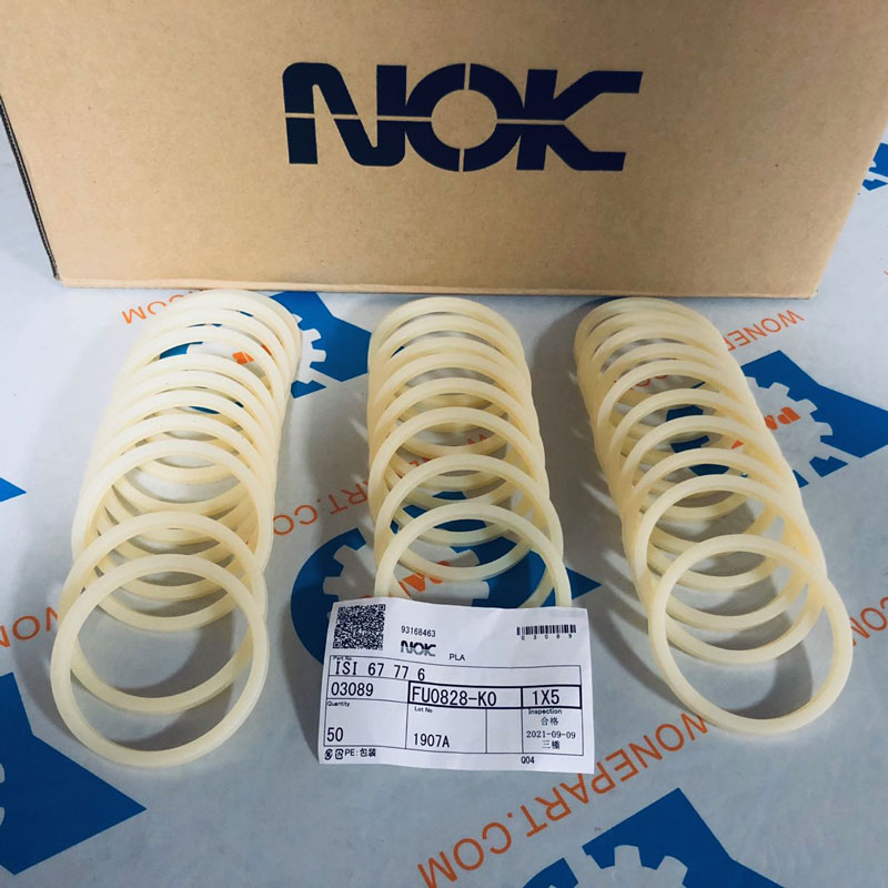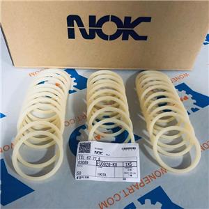

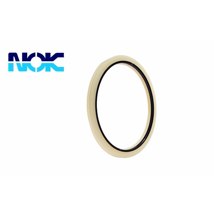
- NOK
- Japan
- 10 days
- 100000 pcs
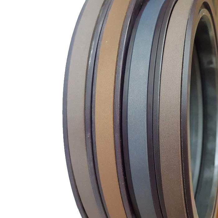
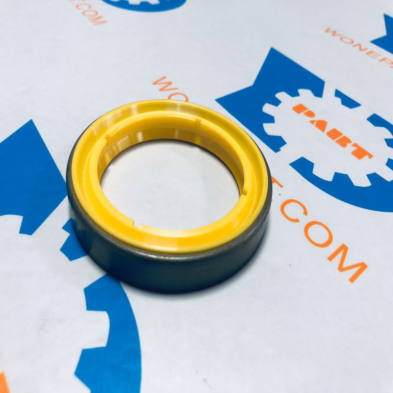
Buffer seal is used in combination with rod packing to absorb the impact and fluctuating pressure at high load, to isolate high temperature fluid, and to improve the durability of the packing. The cylinder is cushioned and sealed, and the product itself has a pressure relief groove for easy exhaust. Robust design.
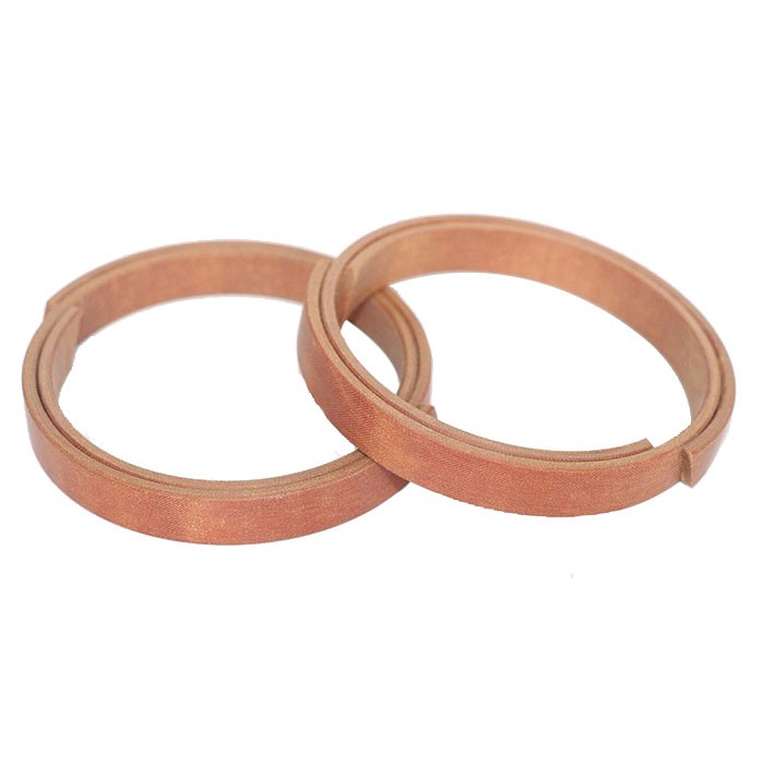
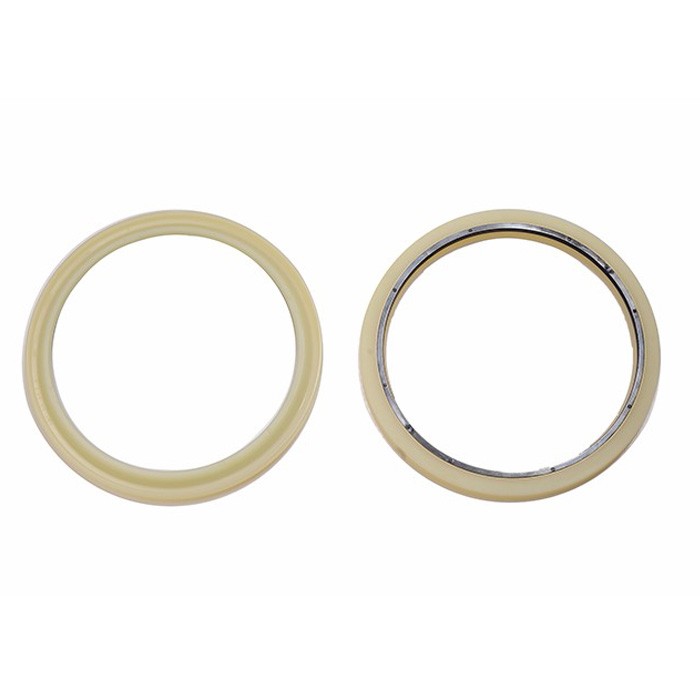
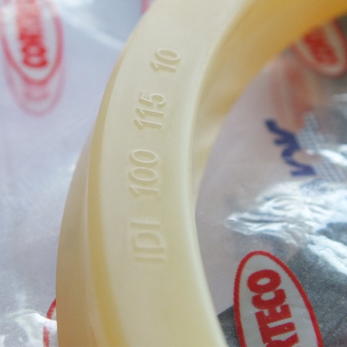
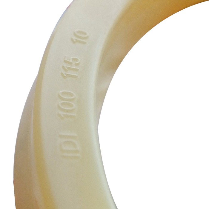
Material: PU+Nylon; PTFE+Rubber+Nylon; PU;
We have Original NOK Japan brand and other OEM brand.
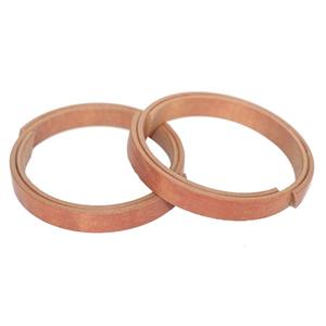
BUFFER SEAL

Buffer seal is used in combination with rod packing to absorb the impact and fluctuating pressure at high load, to isolate high temperature fluid, and to improve the durability of the packing.
The cylinder is cushioned and sealed, and the product itself has a pressure relief groove for easy exhaust. Robust design.

When the hydraulic cylinder is used under high pressure, a polyurethane buffer seal is installed in front of the piston rod main seal to filter the impact of the high pressure on the main seal and to extend the service life of the main seal.
The traditional buffer seal adopts a split structure and includes two parts: a buffer seal body 1 and a retaining ring 2, as shown in FIG. 1. One side of the buffer seal body 1 is provided with a smooth V-shaped groove at the bottom, and the other side is provided with an oil groove 10 (generally, four oil grooves are provided on the top of the buffer seal). The retaining ring 2 is rectangular and cooperates with the bottom of the unslotted side of the buffer seal body 1 (that is, the side with the oil groove 10). The buffer seal body 1 and the rectangular retaining ring 2 are processed separately. When in use, the rectangular seal ring 2 is assembled to the bottom of the buffer seal body 1 to improve the anti-extrusion performance of the buffer seal.
This split buffer seal has the following defects in use:
1. During the operation of the hydraulic cylinder, a pressure P will form between the piston rod main seal and the buffer seal, as shown in Figure 2. When the hydraulic system pressure is released, a back pressure on the buffer seal will be formed there. This results in reverse extrusion deformation of the buffer seal, failure of the buffer function, damage to the sealing system, and eventually leakage of the cylinder.
2. The split buffer seal is subject to pressure during operation, and relative movement will occur between the buffer seal body and the retaining ring, which will increase the wear of the buffer seal.
3. The split buffer seal needs to be installed twice during installation, and the up-down direction of the retaining ring is easy to be reversed.
4. The body and the retaining ring of the split buffer seal need to be produced separately, resulting in higher production, packaging, transportation, and use costs.
Technical realization elements:
The technical problem to be solved by the utility model is to provide a buffer seal, which has excellent anti-extrusion performance and long service life.
In order to solve the above technical problems, the buffer seal of the present utility model includes a body and a retaining ring. A groove is formed on the top of one side of the body, and an oil groove is formed on the top of the other side. The bottom of one side of the groove is matched with the shape of the bottom; the contact surface between the retaining ring and the bottom of the body is stepped.
The material of the body is preferably polyurethane with Shore hardness ShA93-95, and the material of the retaining ring is preferably nylon or polyformaldehyde.
Preferably, the two side walls of the groove can be recessed inward below the middle, so that a lower buckle structure is formed in the lower half of the groove.
The cross section of the retaining ring is L-shaped. A boss can be set at the bottom of the retaining ring. The number of the bosses is 2-12, preferably 6 and evenly distributed on the bottom of the retaining ring.
Preferably, the buffer seal adopts an integrated structure, and the body and the retaining ring are integrally formed.
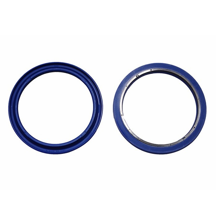
Based on NOK standard, buffer seals including HBY

Material: PU+Nylon; PTFE+Rubber+Nylon; PU;
Color: As per customer request if you have large quantities;

Compared with the traditional split buffer seal, the buffer seal of the present invention has the following advantages and beneficial effects:
1. The buckle design in the groove of the buffer seal body can increase the contact stress of the lip of the buffer seal when the pressure of the hydraulic system increases, thereby improving the sealing performance of the buffer seal.
2. The contact surface of the retaining ring and the buffer seal body is stepped, which increases the support area of the retaining ring to the buffer seal body, thereby improving the anti-extrusion performance of the buffer seal.
3. The design of the boss is added at the bottom to make the hydraulic oil easily flow to the outside, which helps to unload the pressure, plays a role in eliminating back pressure, and avoids reverse extrusion deformation caused by the back pressure of the buffer seal.
4. All parts of the buffer seal are integrally formed, which not only makes production, installation, transportation, and use more convenient and lower cost, but also does not cause relative movement between the parts during work, thereby avoiding the wear of the buffer seal. Extend the service life of buffer seals.
detailed description
In order to have a more specific understanding of the technical content, characteristics and effects of the present utility model, the technical solution of the present utility model is described in detail as follows with reference to the drawings and specific embodiments:
As shown in FIGS. 3 to 5, the buffer seal in this embodiment is a two-material integrated buffer seal, which has a circular ring shape as a whole, and includes an integrally formed buffer seal body 1 and a retaining ring 2.
The material of the cushion seal body 1 is a polyurethane having a Shore hardness ShA94. One side top of the buffer seal body 1 is provided with a groove with an approximately V-shaped cross section, and the other side top is provided with four oil grooves 10 uniformly. The bottom of the groove has a smooth arc shape. The two side walls of the groove are recessed inward in the middle, so that the width of the lower half of the groove is widened to form an inverted buckle 8 structure. This inverted structure can increase the contact stress of the lip of the buffer seal (ie, the opening of the groove) when the pressure of the sealing system increases, and ensure the sealing performance of the lip. The bottom of the buffer seal body 1 on the side where the oil groove 10 is opened is recessed inward in a step shape.
The retaining ring 2 is made of nylon and has an L-shaped cross-section. Six bosses 9 are evenly arranged at the bottom. The retaining ring 2 is matched with the bottom of the side of the buffer seal body 1 which is not grooved (that is, the side where the oil groove 10 is opened at the top), and the contact surfaces of the two are stepped. The retaining ring is made of nylon, which can improve the anti-extrusion and abrasion resistance of the buffer seal. Designing the contact surface of the retaining ring 2 and the bottom of the buffer seal body 1 in a stepped shape can increase the support area of the retaining ring on the buffer seal body 1 and improve the anti-extrusion performance of the buffer seal. Adding a boss at the bottom of the retaining ring 2 can make the hydraulic oil easily flow to the outside to facilitate pressure unloading, eliminate the effect of the back pressure on the buffer seal, and avoid the buffer seal from being damaged due to the back pressure.
The buffer seal can be produced by one-shot injection molding with a rotary two-color injection machine